From the book “Volvo P1800-from idea to prototype and production” by Mats Westerman (Eriksson) and Kenneth Collander
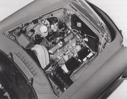
Volvo P1800 was the first car in Volvos program where the new five- bearing crankshaft engine was applied. The new four-cylinder engine was designed with a five-bearing crankshaft and with the possibility of being enlarged to two litres. Therefore it was originally designed as a two litre engine and scaled down because it was decided that 1,8 litre was enough to start with. Thus the B18 engine was borned. Even if it looked like its predecessor, it was a new design except for some small details
In order to meet the weight requirements. aluminium was considered for components that were not going to carry pulsating loads. Thus the bell housing, oil pump and water pump, among other details, were made from aluminium, some of them press cast. This resulted in an increase in weight limited to just a few kg compared to the anticipated increase of 8-10 kg. At the time of the introduction, the engine had an 84,1 x 80,0 mm bore and stroke with 1,780 cc capacity. The weight was only 143 kg thanks to the use of aluminium, In its B18B version, the engine developed 100 hp at 5,500 rpm with a compression ratio of 9.5:1.
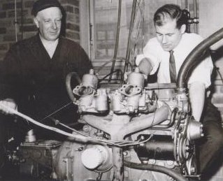
In total, 40 prototype engines were used up until the production start at a cost of one million Swedish crowns. Each engine had a cost of 25,00 crowns. On the test beds, the Volvo technicians carried out thousands of function and durability tests. A number of engines had also been used for road tests, covering a total of one million kilometres, or more that 600,000 miles. A lot of the work focused on the design and function of the combustion chamber with the high 9,5 compression, the function of the valve mechanism at high engine speeds, the five bearing crankshaft and an effective water-cooled oil-cooler. It became evident that no combustion problems whatsoever arose with the chosen compression ratio, using Swedish 97 octane fuel,marked as Premium in those days. Engines were loaned to a number of oil companies who ran their own laboratory tests, reaching the same result as Volvo who in their turn could continue their test programme. The new crankshaft running in five bearings was supposed to make the engine run quieter than its predecessor, which it did, and it could easily handle, without any modifications, a considerably higher compression ratio. The oil-cooler had been designed to cope with very high oil temperatures, as a result of much driving at high engine speeds. It also contributed to a quicker warming of the oil when driving at low speed in coll weather, which prevented the forming of sludge.
In total more than 20,000 hours were spent in the work of producing the engine from start to finish: specification and general description 1,650 hours, testing engine versions 9,000 hours, follow-up and development until production 10,000 hours. Thee work did not end with this of course. During the entire production-life constant follow-up work and improvements were carried out.
Some engine details are worth mentioning. The crankshaft was designed with five main bearings, with 63,5 mm diameter and a diameter of 54 mm for the big end conrod bearings. All stubs were hardened and both the main bearing and the big end shells were made from indium plated lead bronze with steel shells. The robust crankshaft could take very high loads, caused by hard driving on a high compression ratio. It also made the engine run very smoothly and quietly, The pistons were, as usual for this kind of engine, light alloy with cast in steel pieces for the control of axial play and adaption to the load conditions. They had two compression rings, the upper one chromed, and an oil scraping ring. To cope with all sorts of loads. the gudgeon pins used were 22 mm diameter.
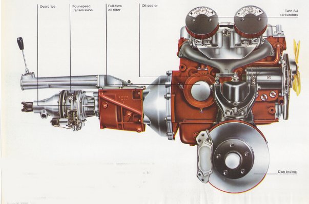
The cylinder block was cast iron with substantial flanges for the flywheel housing and starter motor , again for high load reasons. The alloy housing was conical in order to be rigid enough to take both the four-speed gearbox and the slightly heavier over drive gearboxes

The cylinder head used the same material, with four separate ports on the inlet side, fed two and two by twin carburettors. The were British SU type HS-6 with 1,3/4″ diameter. The combustion chambers were carefully machined which permitted the engine to operate on 97 octane fuel, with 9.5:1 compression ratio without any pinking or back fire tendencies. Cooling ducts surrounded the spark plug holes making the engine practically insensitive to the plug used. The water pump fed the coolant straight into the cylinder head where a distribution pipe made sure that hottest sections were adequately cooled. From the head, the coolant passed down into the block where it quickly heated up and through the thermosyphon principle rose to the upper part of the block and then via the thermostat back to the radiator again. The effective cooling was one reason for the insensitiveness for pinking and back firing of the engine- Furthermore. a quick heating up of the engine meant less cylinder wear and thus better durability.
The oil pump was of gear wheel design, fed the bearings directly through a full-flow filter which effectively cleaned the oil. In order to avoid oil sump whipping and foaming tendencies, the reduction valve of the system was positioned in the oil pump housing, This made the reduction oil from the oil pump pressure side go directly to the inlet side instead of – as was common practice – be sprayed out into the sump. Of course sometimes extremely high oil temperatures could be caused by the ambient conditions. Therefore the oil cooler was fitted to handle this by lowering the oil temperature some 20 – 40 C. During the heating up of the engine after a cold start, it also acted as a oil heater, enabling the oil to reach working temperature more quickly.
In order to keep an eye on the engine , an electric revcounter was fitted to the car, connected to the distributor, The red marking began at 6,000 rpm with an alert marking covering the dial between 5,500 and 6,000 rpm. In general, the car had what the Germans call “Autobahnfestigkeit” below 5,000 rpm, in other words it could be driven for hours and hours at that speed. After 6,000, the valves were most likely to flutter.
The new engine was thoroughly tested before it was put in production. Sometimes it was run for 500 hours at full power. It could without any major engine damage be taken to 6,200 – 6,500 rpm (if the valves followed) and the crankshaft was strong enough to handle up to 7,800 rpm. The development potential was largely improved by the separate inlet ports, instead of siamesed ports as on earlier Volvo engines. The B18B drove through an 8,5″ Borg & Becker clutch and a four-speed cast iron gearbox, the Volvo M40 with beefier bearings an aluminium cover and a gear lever extension. A Laycock-de-Normanville electric overdrive was optional, using a 0,76:1 final drive ratio. With OD the final gear ratio was 4.56:1 otherwise the standard was 4.10:1
The most significant difference between the B16 and the B18 engines were the crankshaft, the cast in pushrod tunnels and the pipe connections. An Amazon with registration number OA6427 (OA like O being the Gothenburg area) was used with P1800 configuration in Skövde by Pentaverken and another X2-B16 engine was tried out in one of the British-built prototypes. The were constantly running in order to accumulate as much experience as possible. According to engine genius Per Gillbrand, the engine was very stable in the crank but due to its internal friction and subsequent thirst for fuel, it was much criticized by people in the engine department. One positive thing about it though was that it never got the so-called B16 disease; when one of the main bearings was clogged by oil, the nearest bearing behind it seized.
An unusual detail of the B18B was the oil cooler which had been modelled on the type of radiator used for the Penta marine engines. It constituted heat exchange oil-to-water in the form of a 180 mm diameter disc with 25 mm thickness. It fitted to the right side of the block. The oil filter in turn was fitted on top of the oil cooler. The cooler was used for the B18 engines until the introduction of the B20 engine in 1968, when the high quality oils had been developed that could better cope with high temperatures. Erling Kurt comments: “We decided to try this solution because we had oil temperatures that reached 170-180 C, far too high for the oils of the day but thanks to the oil cooler we could lower these temperatures by 20 – 30 C” It was difficult to manufacture but we got it working just fine” The cooler had a steel case and contained a number of thin brass sandwich plates which would easily crack due to variations of pressure in the lubrication system. Test after test were done and at last the engineers made the oil cooler stand up to 200,000 pressure cycles during a laboratory test which was considered adequate for production.
All the pre-requisites finally resulted in an engine:
Type: B18B
Cylinder diameter: 84,14 mm (3.5/16″)
Stroke: 80 mm
No. of cyliders: 4
Swept volume; 1.78 litres
Power output: 100 hp SAE at 5,500 rpm
Powet to litre ratio: 56 hp SAE
Torque 15kpm (147 Nm) at 4,000 rpm

|
|
|